
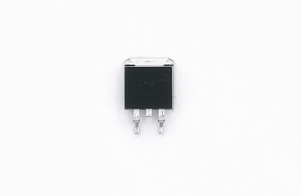
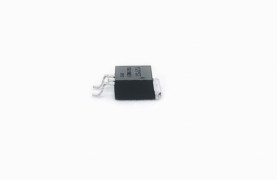
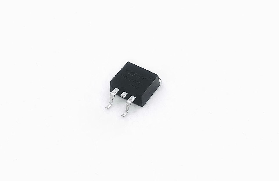
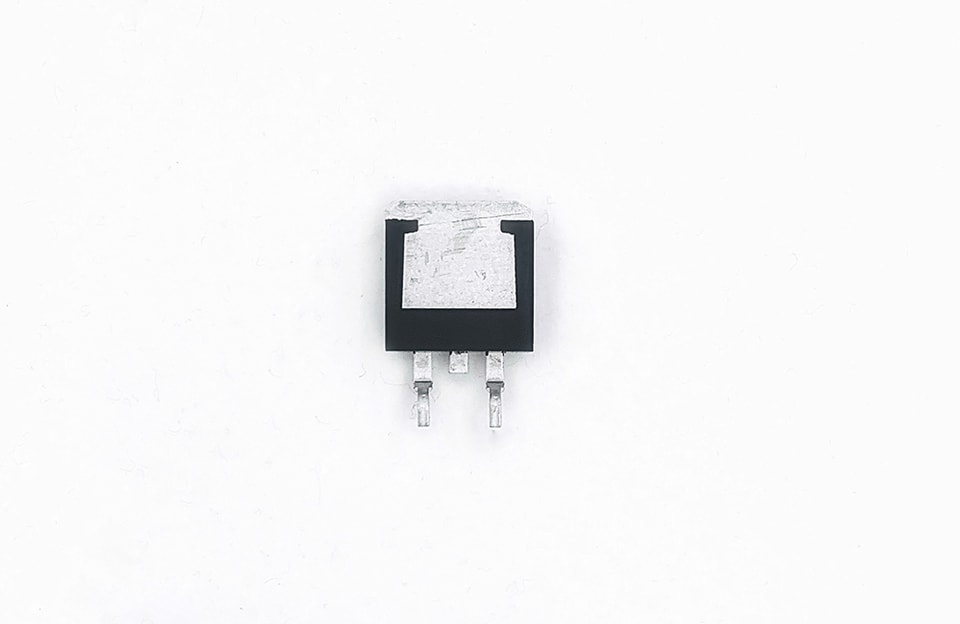
YZPST-G15N65T
Tip: include the part number, target voltage/current and application environment.
Downloads & technical files

Max Junction Temperature 150°C
High breakdown voltage up to 650V for improved reliability
Short Circuit Rated
Very Low Saturation Voltage:
VCE(SAT) = 1.65V (Typ.) @ IC = 15A
Soft current turn-off waveforms
VCE | 650 | V |
IC | 15 | A |
VCE(SAT) IC=15A | 1.65 | V |
Soft switching applications
Air conditioning
Motor drive inverter

Product | Package | Packaging |
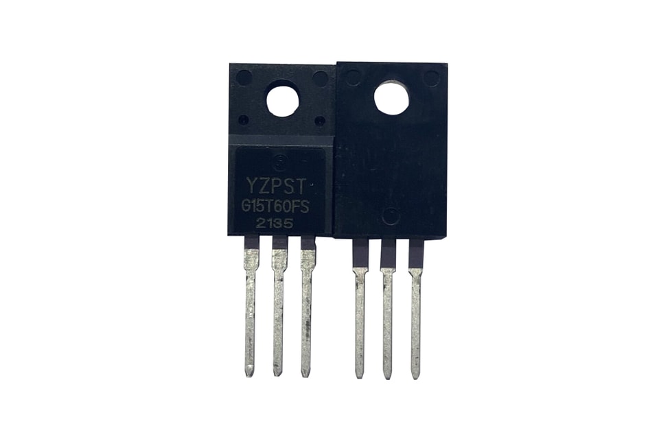
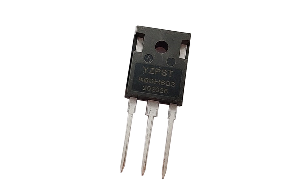
YZPST-15N65T1 | TO-220 | Tube |
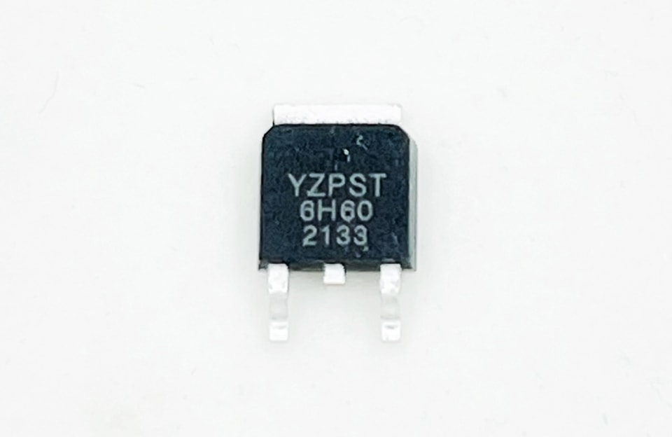
YZPST-15N65T1 | TO-263 | Tube |
YZPST-15N65T1 | TO-220F | Tube |
Parameter | Symbol | Value | Unit |
Collector-Emitter Breakdown Voltage | VCE | 650 | V |
DC collector current, limited by Tjmax
TC = 25°C
TC = 100°C
| IC |
30
15
| A |
Diode Forward current, limited by Tjmax
TC = 25°C
TC = 100°C
| IF |
30
15
| A |
Continuous Gate-emitter voltage | VGE | ±20 | V |
Transient Gate-emitter voltage | VGE | ±30 | V |
Turn off safe operating area VCE ≤650V,
Tj ≤ 150°C
| - | 60 | A |
Pulsed collector current, VGE=15V, tp limited by Tjmax | ICM | 45 | A |
Short Circuit Withstand Time, VGE= 15V, VCE≤ 400V | Tsc | 5 | μs |
TO-220F Power dissipation , Tj=25℃ | Ptot | 27 | W |
TO-220,TO-263, Power dissipation , Tj=25℃ | Ptot | 105 | W |
Operating junction temperature | Tj | -40...+150 | °C |
Storage temperature | Ts | -55...+150 | °C |
Soldering temperature, wave soldering 1.6mm (0.063in.) from case for 10s | - | 260 | °C |
Thermal Resistance
Parameter
| Symbol | TO-220,TO-263 | TO-220F | Unit |
IGBT thermal resistance, junction - case | Rθ(j-c) | 1.2 | 4.9 | K/W |
Diode thermal resistance, junction - case | Rθ(j-c) | 2.38 | 5.8 | K/W |
Thermal resistance, junction - ambient | Rθ(j-a) | 62.5 | K/W | |
Electrical Characteristics of the IGBT(Tj= 25℃ unless otherwise specified)
| Symbol | Parameter | Test Conditions | Min. | Typ. | Max. | Units |
Static Characteristics (Tested on wafers) | ||||||
BVCES |
Collector to Emitter Breakdown
Voltage
| VGE = 0V, IC = 1mA | 650 | - | - | V |
VCE(SAT) |
Collector to Emitter Saturation
Voltage
| IC = 15A, VGE = 15V | - | 1.65 | 1.95 | V |
VGE(th) | G-E Threshold Voltage | VGE = VCE, IC = 250μA | 4.1 | 5.0 | 5.7 | V |
ICES | Collector Cut-Off Current | VCE = 650V, VGE = 0V | - | - | 25 | μA |
IGES | G-E Leakage Current | VGE = ±20V, VCE = 0V | - | - | ±200 | nA |
gfs | Transconductance | VCE=20V, IC=15A | - | 10 | - | S |
Parameter | Symbol | Conditions | Min | Typ | Max | Unit |
Dynamic | ||||||
Input capacitance | Cies |
VCE = 25V, VGE = 0V, | - | 990 | - | pF |
Output capacitance | Coes | - | 56 | - | ||
Reverse transfer capacitance | Cres | - | 30 | - | ||
Gate charge | QG | VCC = 480V, IC = 15A, VGE = 15V | - | 92 | - | nC |
Short circuit collector current | IC(SC) |
VGE=15V,tSC≤5us VCC=400V, | - | 98 | - | A |
| Parameter | Symbol | Conditions | Min. | Typ. | Max. | Unit |
Dynamic | ||||||
Turn-on Delay Time | td(on) |
Tj=25°C VCC = 400V, IC = 15A,
VGE = 0/15V, Rg=12Ω
| - | 15 | - | ns |
Rise Time | tr | - | 25 | - | ns | |
Turn-off Delay Time | td(off) | - | 60 | - | ns | |
Fall Time | tf | - | 46 | - | ns | |
Turn-on Energy | Eon | - | 0.75 | - | mJ | |
Turn-off Energy | Eoff | - | 0.1 | - | mJ | |
| Parameter | Symbol | Conditions | Min | Typ | Max | Unit |
Dynamic | ||||||
Diode Forward Voltage | VFM | IF = 15A | - | 1.7 | - | V |
Reverse Recovery Time | Trr |
IF= 15A VR = 300V, | - | 50 | - | ns |
Reverse Recovery Current | Irr | - | 4 | - | A | |
Reverse Recovery Charge | Qrr | - | 83 | - | nC | |


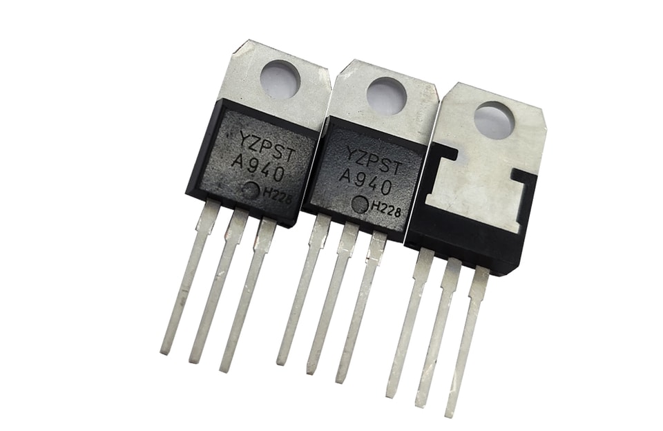
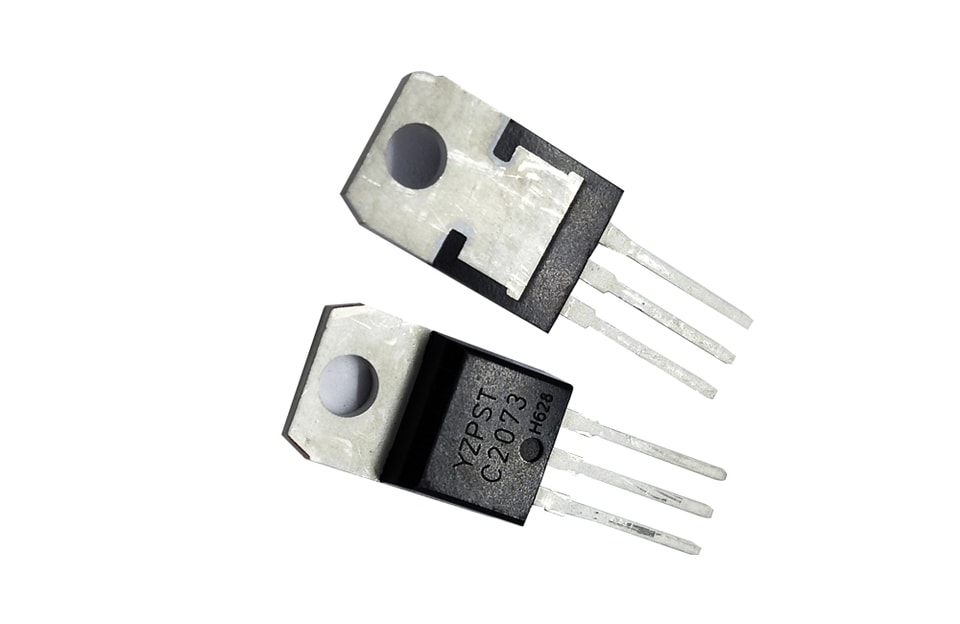

Power semiconductor devices, protection components and industrial power solutions.


