.jpg)
.jpg)
.jpg)
.jpg)
YZPST-P150HFN120AT1R6
Tip: include the part number, target voltage/current and application environment.
Downloads & technical files

P/N:YZPST-P150HFN120AT1R6
62mm module with fast Trench/Fieldstop IGBT and Fast Recovery Diode
Features
■ Low Switching Losses
■ LoW VcEsal
■ Low VcE(sat with Positive Temperature Coefficient
Applications
■ Motor Drives
UPS Systems
■ High Power Inverter
Equivalent Circuit Schematic
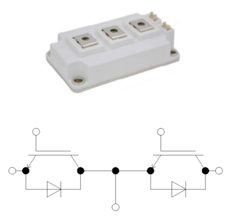
IGBT -Inverter
Maximum Rated Values
Symbol | Description | Conditions | Values | Unit |
VcEs | Collector-Emitter Voltage | Tv=25℃ | 1200 | V |
VGEs | Gate-Emitter Peak Voltage | Ty=25℃ | ±20 | V |
lc | Continuous DC Collector Current | Tc=100℃ | 150 | A |
CRM | Repetitive Peak Collector Current | tp=1ms | 300 | A |
Ptot | Total Power Dissipation | Tc=25℃,Tyjmax=175℃ | 1500 | W |
Characteristic Values
| Symbol | Values | |||||
| Description | Conditions | Min. | Typ. | Max. | Unit | |
| VcE(sat | Collector-Emitter Saturation Voltage | VcE=15V,Ic=150A,Tv=25℃ | 2.2 | V | ||
| Vge=15V,Ic=150A,Tv=125℃ | 2.5 | V | ||||
| VgE(th | Gate Threshold Voltage | VgE=VcE,Ic=3.8mA | 5 | 5.8 | 6.5 | V |
| IcEs | Collector-Emitter Cut-Off Current | VcE=1200V,VgE=0V | mA | |||
| GES | Gate-Emitter Leakage Current | VcE=20V,VcE=0V | 600 | nA | ||
| RGint | Internal Gate Resistor | Ty=25℃ | 3.8 | Ω | ||
| Cies | Input Capacitance | 11.5 | nF | |||
| Coes | Output Capacitance | Vce=25V,Vce=0V,f=1MHz | 1 | nF | ||
| Cres | Reverse Transfer Capacitance | 0.4 | nF | |||
| tt(on) | Turn-on Delay Time | 139 | ns | |||
| Vcc=600V | ||||||
| t | Turn-on Rise Time | VoE=±15V | 37 | nS | ||
| d(a) | Turn-off Delay Time | Ic=150A | 192 | nS | ||
| t | Turn-off Fall Time | Rg=2.0g | 128 | nS | ||
| Eon | Turn-on Switching Loss | Inductive Load | 7.9 | -= | mJ | |
| E₀ff | Turn-off Switching Loss | Ty=25℃ | 8.4 | mJ | ||
| Isc | Short Circuit Data | VcE≤15V,Vcc=600V | 518 | A | ||
| tp≤10μs,Tv=25℃ | ||||||
| Thermal Resistance,Junction to Case | Per IGBT | —-- | 0.1 | —-- | K/W | |
| Twop | Virtual Junction Temperature | Under Switching | -40 | 150 | ℃ | |
Diode -Inverter
Maximum Rated Values
Symbol | Description | Conditions | Values | Unit |
VRRM | Repetitive Peak Reverse Voltage | Tv=25℃ | 1200 | V |
lF | Continuous DC Forward Current |
| 150 | A |
lFRM | Repetitive Peak Collector Current | tp=1ms | 300 | A |
Characteristic Values
| Symbol | Values | |||||
| Description | Conditions | Min. | Typ | Max. | Unit | |
| Forward Voltage | lr=150A,Vse=0V,Tv=25℃ | 2.5 | V | |||
| VF | l=150A,Vge=0V,Tv=125℃ | 1.9 | —-- | V | ||
| RM | Peak Reverse Recovery Current | —-- | 42 | A | ||
| Qr | Recovered Charge | l=150A,Vg=600V,Vge=-15V | 3.1 | uC | ||
| Erec | Reverse Recovery Energy | Ty=25℃ | 1.1 | mJ | ||
| Tuop | Virtual Junction Temperature | Under Switching | -40 | 150 | ℃ | |
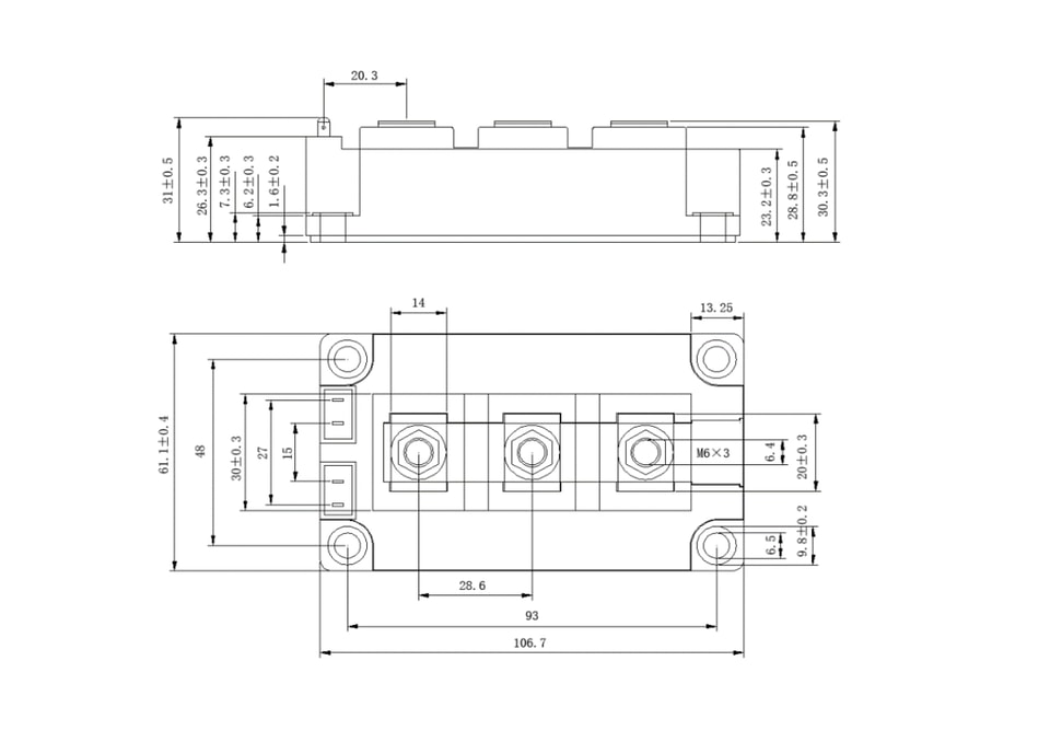
Package Outlines(mm)
.jpg)
.jpg)

Power semiconductor devices, protection components and industrial power solutions.


